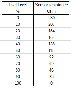
 Brian had mentioned to me before I took on this car that the coolant temperature and fuel tank content gauges didn’t seem to tell the truth and to some extent they appeared to give readings that were influenced by the other. After driving the car a little I agreed and set out to understand whether this was ‘normal’ behaviour or a fault. I found that the Voltage Stabiliser was faulty and replaced it with a modern regulator.
The Smiths dash gauges used in 1968 used a bimetallic strip attached to the pointer, which was heated by a small resistive heating element. With a current flowing in the heating element, the bimetallic strip bends and the indicator moves across the gauge. It appears to be something of a mystery how the gauges themselves are calibrated, but a quick search on the net shows that the internals of the fuel and coolant gauges are identical.
With such a simple heat based system, the Voltage supplied to the circuit is critically important to provide a calibrated reading, so a Voltage Stabiliser is fitted behind the Elan Tachometer that takes an ignition live and creates a ‘regulated’ 10 Volt supply for just these two gauges. But semiconductors were still pretty new then and the established way to provide this regulation was to use a second bimetallic strip and heater in the stabiliser to open and close a pair of contacts. The 10V supply to the gauges was therefore simply an on-off pulsed supply in which the duty cycle provided an ‘average 10V’ supply that the gauges tolerated as they were slow to respond and damped out almost all of this pulsing behaviour.
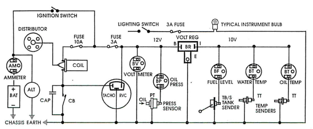
Generic Smiths gauge wiring diagram
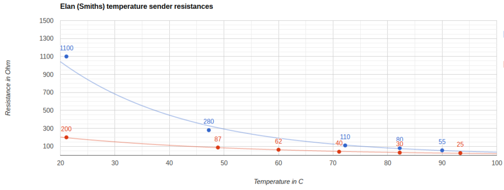
As a first look, I used my portable oscilloscope to look at the pulse waveform at the temperature sender, as this is the most accessible place to connect to it. With the engine cold, that sensor has a resistance of over 1000 Ohm, which decreases to a few tens of Ohm when hot. I plotted this behaviour for the two sensor types commonly discussed on the lotuselan.net forums, which clearly shows that it’s important to get the correct sensor.
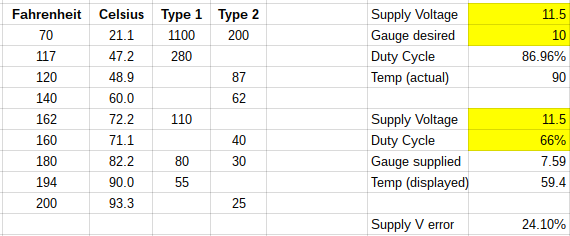
For my test, the engine was off and the coolant temperature sensor was disconnected; the oscilloscope was connected to the sensor wire (which connects directly to the gauge and through that to the stabiliser). What I got was a (approximately) 12V square wave, with 66% duty cycle and a pulse rate of approximately 1.5Hz, which varied a little. Calculating the average Voltage shows that the gauge supply is indeed less than 10V (just under 8V in this case) and so the stabiliser was suspect.
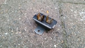 Armed with the Elan circuit diagram and my borescope (to see into the confined space behind the dash) I found the stabiliser and rather than buy a direct replacement, used a simple adjustable switched mode power supply that I had in stock. Overkill perhaps, as this
 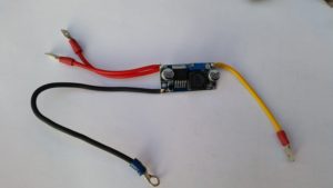 can source 3 Amps, but at only about £2 delivered, I have found these useful to have in my parts box. The photo shows the board with wire tails soldered to it.
There are two red wires, as these connect to the two Red/Green wires at the supply side of the original stabiliser and I have used a yellow wire (no green in my box) for the output, onto which a female spade connector was soldered to connect to the solid Green wire supplying the two gauges. A Black wire with a ring connector was soldered on to provide the Earth connection at the original earthing point on the back of the tacho gauge, the output Voltage adjusted to 10V and the whole thing shrouded in heat shrink tubing and hidden in the dash.

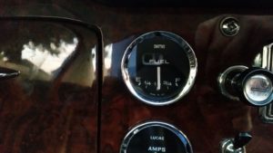 The result is that the car now has stable gauges, reading slightly higher than before. Of course I don’t know just how accurate they are yet, I believe there to be between 6 and 7 gallons of fuel in the tank and the gauge shows just over 1/2 full. The coolant temperature was measured using an optical thermometer pointed at the thermostat housing right next to the temperature sender, which read 85 degrees C with the gauge showing just left of 90 degrees, so this looks reasonable.
Well, the outcome seems to be worth it; while my hi-tech switch mode power supply is far from authentic, I have retained the original stabiliser and didn’t need to modify any wiring to fit the alternative, so it can easily be put back to original later. The positive here is if I was later to determine that the gauges read higher or lower than they should, I can easily adjust my supply to correct them. Similarly it wouldn’t be difficult to split the two gauges onto separate regulators to provide specific corrections to both.
I think Brian would have approved – these gauges should now be consistent and potentially (once I have watched them closely for a while) they could also be considered reliable. The original Voltage Stabiliser, whilst pretty ingenious in its day, is universally acknowledged to be unreliable today and this is a good modification.
I have collected a bit of information along the way that should be useful to anyone following in my steps here – the circuit diagram is good for all Lotus Elan including the Plus 2 (but not M100!) and I believe the wiring colours are also reliable across all similar aged Lotus. I probably don’t need to say this but will anyway – the wiring in these old cars is pretty much a rats nest behind the dash. There are connectors that are perfectly safe while connected but are not insulated and would cause havoc if disconnected and allowed to touch others. Disconnect the battery before disturbing anything!
Parts
- Connectors – (2 male, 1 male and 1 x 6mm ring)
- Regulator – I bought 5 from China on eBay for about £3, but they are available individually in the UK (click here)
- Wire – about 15cm of Red/Green, 8cm of Black, 8cm of Green
- Heatshrink – about 7cm length of 5cm (when flat) tube.
Time
- About an hour – It shouldn’t take much more than an hour, taking it easily. Nothing is difficult except from accessing the original Voltage Stabiliser, which is secured to the back of the tachometer via a post and a knurled finger-nut. Beware, as that nut also secures several other earth connections that will spring off when you remove it!
Tools
- Wire cutters / strippers
- Crimp tool or Mole Grips (to crimp the terminal connectors onto the wire)
- Small ‘terminal’ screwdriver (to adjust the regulator)
- Volt Meter (to set the regulator output Voltage I used a digital multi meter)
- Soldering Iron and solder
- Hot air gun (to shrink heatshrink)
- PVC tape (to cover any dodgy uninsulated terminals you may find!)
- Slim torch (to see in the dark behind the dash)
Technical Information
The following are pieces of information I’ll probably want to refer back to someday, so I thought I would include them here and share with everyone else. The circuit diagram is hand-drawn for speed, and taken directly from the Workshop Manual for the Elan Plus 2. (circuit diagram coming soon)
I also created a spreadsheet to help understand the likely performance impacts on my original system, as well as plotting the sensor resistances against temperature and fitting exponential curves against them. The source data for these curves isn’t mine – I derived it from here to help identify my sensor in case I ever need to buy a replacement. The figures in the table under Type 1 and Type2 are the resistances of the sensor in Ohm at the specified temperature.
![[Abs-Zero]](http://www.abs-zero.com/wordpress/wp-content/uploads/2013/11/abs-zero.jpg)

